Using the Support Designer
You can use the Support Designer for the following tasks.
Creating location plans
You can use the Support Designer to create location plans for supports. At least one location plan must exist to add supports.
A location plan defines the boundaries of a 3D space that can contain supports. You need to decide whether to create a single location plan for the entire model area or multiple smaller location plans based on factors such as logistics areas or disciplines.
When you create a new location plan, it is assigned to the 'Support' system by default. If needed, you can change the system later through the Properties pane.
Tip: Creating a location plan is not specific to discipline, so you can be on any of the following tabs: Piping, Ducting, or Cabling.
Do the following:
-
On the Piping, Ducting, or Cabling tab, select Support > Location plans.
-
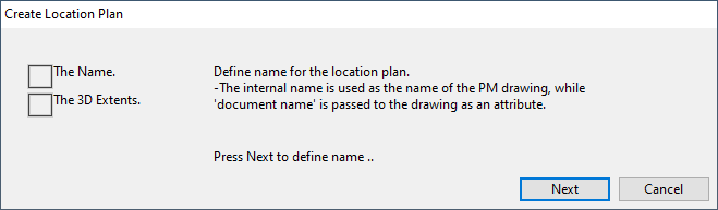
In the Support Designer: Location Plans dialog, click New.
The Create Location Plan dialog opens, displaying the steps you are about to take.
-
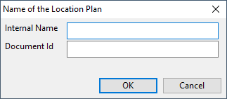
Click Next. The Name of the Location Plan dialog opens.
-
Define the following information:
-
Internal Name – Enter a name for the location plan. Do not use spaces or special characters.
-
Document Id – Enter a name for the location plan document. Do not use spaces or special characters.
Then click OK. The Create Location Plan dialog opens again.
-
-
Click Next. The Set Properties of View dialog opens.
-
Define the area of the location plan in the same way as you define the area for Plant Modeller work views (see Set Properties of View) and click OK. The Create Location Plan dialog opens again.
-
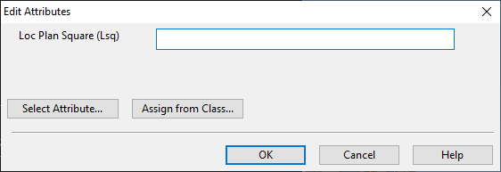
Click Done. The Edit Attributes dialog opens.
-
Enter a value for the "Loc Plan Square" (Lsq) attribute, define any other attributes the location plan should have, and click OK.
The location plan is created and displayed in the list.
You can now start adding pipe supports, air duct supports, or cable tray supports to the location plan.
Creating supports
You can use the Support Designer to add standard or custom supports to a location plan.
Support is a group object—a COS object of type "Support Group"—that functions as a container or handle for the 3D objects that form the actual support construction. If you delete a support group that has 3D objects (primary supports, secondary supports), you are prompted whether to delete just the group, just the objects, or both the group and the objects.
Prerequisites
Do the following:
-
Open the Supports dialog of the required discipline, as described in Pipe, duct, and cable tray supports.
-
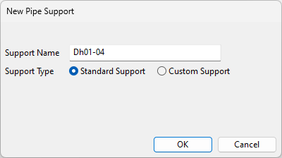
Click New. The New Pipe Support, New Duct Support, or New Cable Tray Support dialog opens.
-
Define the following information:
-
Support Name – Enter a name for the support. Do not use spaces or special characters.
-
Support Type – Select the support type: Standard Support or Custom Support.
-
Document Id – If you chose Custom Support, enter a name for the support document. Do not use spaces or special characters.
-
-
Click OK. The support group is created and displayed in the list.
You can now start adding primary and secondary supports to build the support construction.
Tip: Once you have built the complete support, you can make copies of it as described in Creating supports by copying.
Creating primary supports for pipes
You can use the Support Designer to create primary supports for multiple pipes of different sizes. The pipes can run parallel to each other, but this is not mandatory.
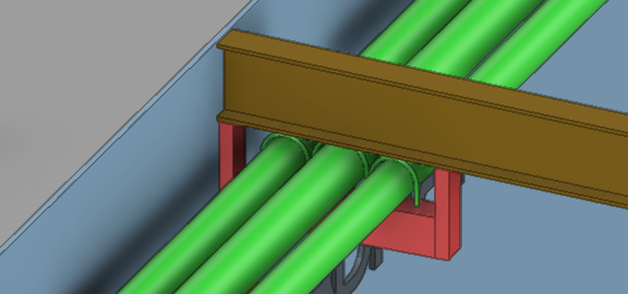
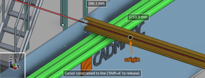
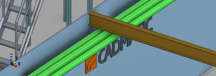
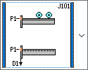
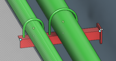
In this example procedure, you insert U-clamps as a primary support component to three horizontal pipes to be supported. The port-type secondary support (red in the picture below) is to be connected to an existing I-beam above the support. The pipe in the middle is larger than the other two. The picture below shows how the support looks when completed.
Prerequisites
-
Administrator has defined a Standard Component for each kind of primary support to be inserted.
Do the following:
-
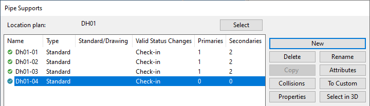
On the Piping tab, select Support > Pipe supports. The Pipe Supports dialog opens.
-
Click Select to change the location plan, if needed.
-
Select the support where you want the primary support to be added.
-
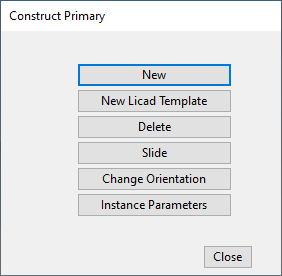
In the Primary section, click Construct. The Construct Primary dialog opens.
-
Click New.
-
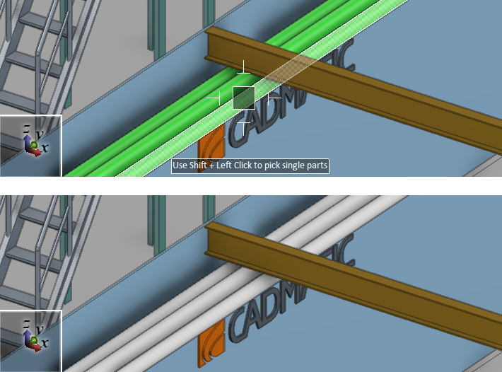
Select a set of straight pieces of pipes, and press Enter to accept the set.
-
Define the support plane to determine how the support construction is positioned in the model.
The program places the primary support at the intersection of the support plane and the pipe centerline and aligns the primary support with the direction of the pipe (which might differ from the direction of the normal). The secondary support the user is to position so that the primary support can be attached to it.
-
Pick the origin point of the support plane.
 Show/hide image
In this example we pick the origin point from the centerline of the I-beam above the pipes.
-
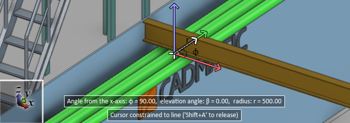
Select the direction of the normal vector of the support plane.
Show/hide image
In this example the pipes are horizontal. We select the direction of the normal to be the same as the direction of the pipes (parallel to Y axis), which positions the support plane vertically, perpendicular to the pipes (parallel to X axis).
-
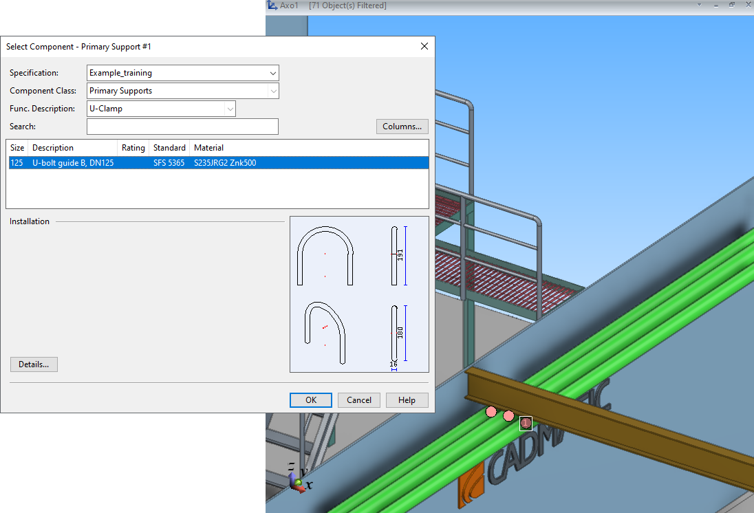
-
In the Select Component - Primary Support #1 dialog, select the Standard Component to use for the first primary support and click OK.
Then do this kind of selection for each additional primary support.
-
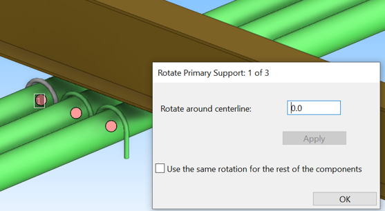
The Rotate Primary Support dialog opens, and the work view displays the number "1" over the first primary support in the insertion sequence. You can click the work view to browse the view; press Esc to return to the dialog.
-
To rotate the first component around the pipe centerline, enter the angle value and click Apply.
-
If the other components require the same rotation, select the option Use the same rotation for the rest of the components.
Show/hide image
In this example, the default rotation 0.0 is OK for all three primary support components, so we can select the Use the same rotation… option to accept the current rotation for all of them.
-
Click OK.
-
If you did not select Use the same rotation…, the Rotate Primary Support dialog opens for each additional primary support component in the set, and the work view indicates the component by displaying a number over it.
The primary supports are added to the model. Collision checking starts automatically, as described in Collision checking for supports.
-
-
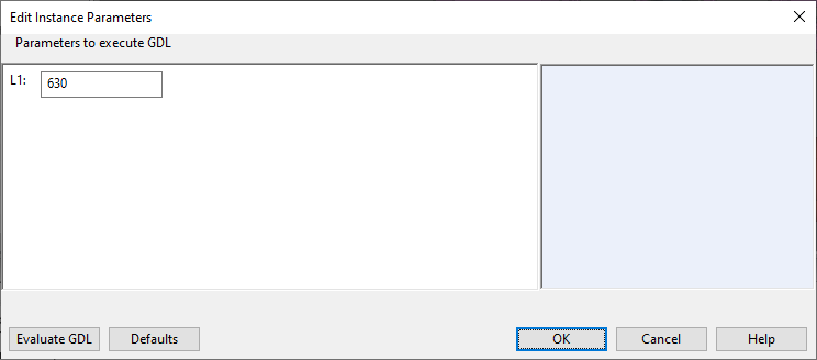
You can adjust the dimensions of a support you inserted, such as the rod length of a hanger, if the associated parameters in the GDL component are defined as instance parameters (see Parameters pane):
Click Instance Parameters, pick the support from the model, and press Enter. The Edit Instance Parameters dialog opens, and you can edit the available dimension values as appropriate.
-
You can now add the secondary support, as described in Creating secondary supports.
Creating primary supports for ducts
You can use the Support Designer to create primary supports for multiple air ducts of different sizes. The ducts can run parallel to each other, but this is not mandatory.
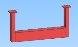
In this example procedure, you insert a flatbar clamp to two straight ducts that are to be supported from a beam that is located above the ducts.
Prerequisites
-
Administrator has defined a Standard Component for each kind of primary support to be inserted.
Do the following:
-
On the Ducting tab, select Support > Duct supports.
-
Select the location plan where you want the support to be added and click OK. The Duct Supports dialog opens.
-
Select the support where you want the primary supports to be added.
-
Insert the first primary support:
-
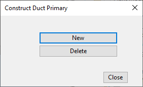
In the Primary section, click Construct. The Construct Duct Primary dialog opens.
-
Click New.
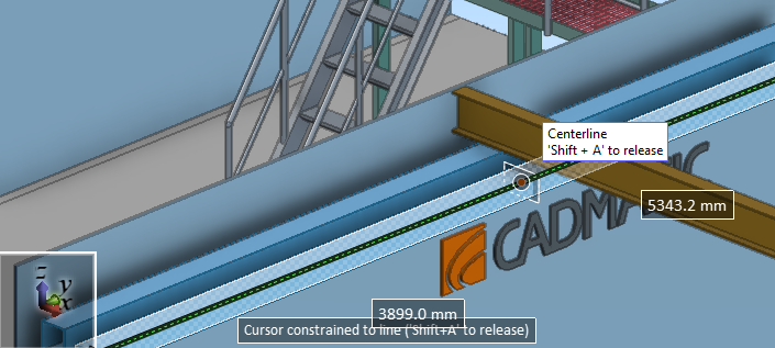
-
Pick the insertion point from the first air duct to be included in the support construction.
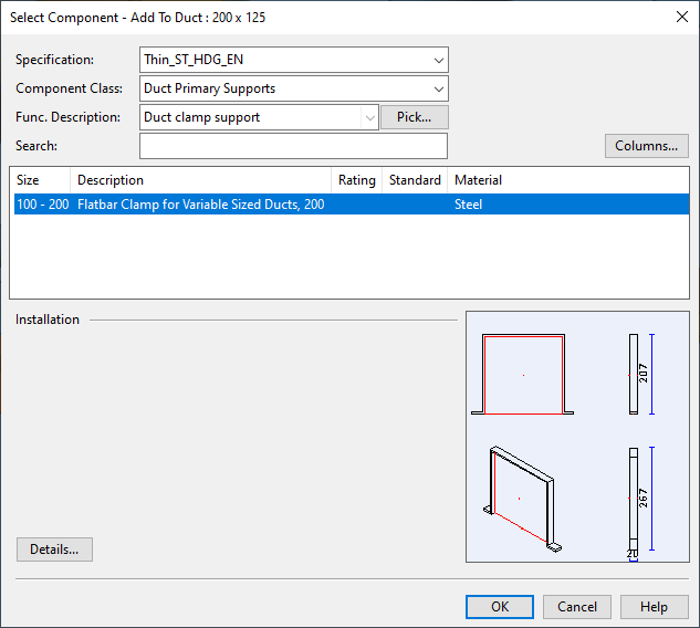
-
In the Select Component - Add To Duct dialog, select the Standard Component to use for the first primary support and click OK.
-
Press Enter to accept the insertion.
Then insert the second primary support in the same way.
-
-
Click Close to stop inserting primary supports.
Creating secondary supports
You can use the Support Designer to create secondary supports for support constructions.
In this example procedure, you insert a port-type pipe support below a horizontal I-beam.
Prerequisites
-
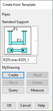
Administrator has defined the required support template in Project Environment > [project] > Configuration > Support Designer, in the configuration object Parameters for custom secondary pipe supports or Parameters for standard secondary pipe supports. (Similarly named configuration objects exist also for ducts and cable trays.) In this example procedure, there is a standard secondary pipe support template called "R205.mac:R205_1".
If the template does not exist, you can still construct the support manually, using beams and objects in the project or library database.
Do the following:
-
On the Piping tab, select Support > Pipe supports.
-
Select the location plan where you want the support to be added and click OK. The Pipe Supports dialog opens.
-
Select the support construction where you want the secondary support to be added.
-
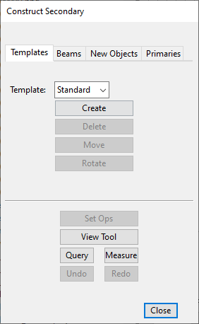
In the Secondary section, click Construct. The Construct Secondary dialog opens.
For general information on this dialog, see Construct secondary.
-
Create the secondary support:
-
On the Templates tab, select "Standard" and click Create. The Create from Template dialog opens.
-
Select the support template to use and click Create.
-
Pick the points that are required to create the support.
-
Click OK to close the Create from Template dialog.
The secondary support is now ready.
-
-
Click Close to exit the Construct Secondary dialog. Collision checking starts automatically, as described in Collision checking for supports.
Creating supports by copying
You can make additional copies of an existing support construction, using either the whole support or just some of its members to create the new instances. The included model objects cannot be members of any existing group, except a primary pipe support can be a member of a pipeline, and the same pipeline membership is applied to all the copies, as well. The attributes of the support are copied, and you are prompted to edit their values for each new copy. Also the attributes of the primary support are copied, without prompting you to edit their values.
Note: The Copy command does not support Undo and Redo.
Do the following:
-
Open the Supports dialog of the required discipline, as described in Pipe, duct, and cable tray supports.
-
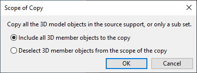
Select the support you want to copy and click Copy. The Scope of Copy dialog opens.
-
Select whether you want to include all members of the support in the copying or to exclude some of them, and click OK.
-
If you selected the "Deselect 3D member objects…" option, pick the objects you do not want to copy, and press Enter to accept the set.
-
Pick a base point for copying and press Space to accept the point.
-
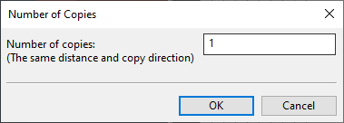
Pick the target point for the first copy and press Space to accept the point. The Number of Copies dialog opens.
-
Specify the number of copies to create (1–99) and click OK. The Location Plan Data dialog opens.
-
Specify the following settings:
-
Position Id – The program suggests the next free position ID for the new support, but you can enter a different ID, if needed.
-
Support Type – Set this to the same type as the support you are copying.
-
Document Id – If copying a custom support, the program suggests the next free ID for the support document, but you can enter a different ID, if needed.
Then click OK.
-
-
If the support you are copying has attributes, the Edit Attributes dialog opens, and you can edit the attribute values or add and remove attributes, as appropriate.
Then click OK.
-
If you selected to create more than one copy, you are prompted to specify a position ID (and possibly attribute values) for each additional support. All the additional copies are inserted in the same direction and with the same amount of spacing that you defined by selecting the base point and the new target point. When all the copies are defined, you return to the Supports dialog.
Creating primary and secondary supports with support wizards
You can use a support wizard to create a support construction that consists of primary and secondary supports.
Prerequisites
- Administrator has created the required wizard.
Do the following:
-
Open the Supports dialog of the required discipline, as described in Pipe, duct, and cable tray supports.
Note: The wizard does not allow you to create supports outside the extents of the location plan.
-
Click New to create a new support construction.
- In the Location Plan Data dialog, do the following:
- Enter a Position ID.
- Select whether to use a Standard Support or Custom Support template.
- If you selected Custom Support, enter a Document ID.
- Click OK.
-
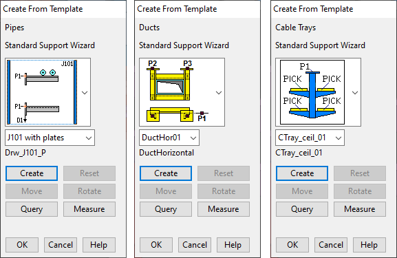
Click Support Wizard. The Create From Template dialog opens, showing the pipe support templates, duct support templates, or cable tray support template, depending on which type you are creating.
-
Open the template drop-down list and select the appropriate template. The thumbnail picture shows you the points (P) and directions (D) that the wizard will prompt you to define.
-
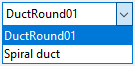
If the template has several variants, select the name of the standard or custom drawing to be displayed in material lists.
-
You can click Query to check object properties from the model or Measure to take measurements, if needed.
-
To start creating the support, click Create.
-
If creating a pipe support, select the parallel pipes to be supported, one by one, by clicking a pipe and then pressing Enter to accept it. Then accept the set of pipes by pressing Enter or Esc.
-
Define the requested points, such as the fixing point of the support in a wall, by clicking the point.
-
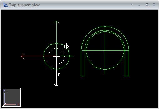
Define the requested secondary support directions, such as the direction of an L-bar, by using the on-screen tools.

-
Define the requested primary support directions, such as the direction of a U-clamp, by using the on-screen tools.
A temporary view opens for selecting on which side of the pipe to place the secondary support. We recommend using the arrow keys, as this makes it easy to select a direction that is along a main axis.
With everything defined, the support is added to the model.
-
If the support does not look as expected, you can use these tools:
- Click Move to change the secondary support's location.
- Click Rotate to change the secondary support's orientation.
- Click Reset to remove the whole support.
-
Click OK to close the support wizard.
Using multi-pipe clamps as primary supports
Support structures usually have one primary support, such as a U-clamp or pipe slide, per supported pipe. A multi-pipe clamp is a special type of primary support that can be used to support several pipes.
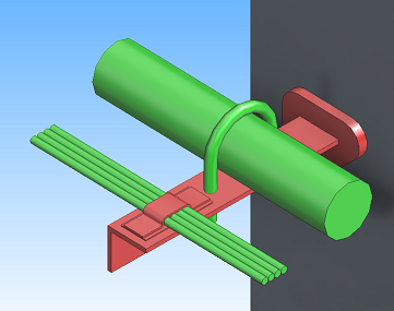
Administrator can configure any pipe support wizard to allow multi-clamps to be used, either together with normal primary supports (as in the picture above) or as the only primary support.
Normally, Support Wizard selects the primary support components automatically, by taking the "su4" Short Code from the active specification and using the referenced Catalog Part as the primary support. If the referenced part is a multi-pipe clamp, it will prompt the user to select the component manually, but also this can be set up to be automatic.
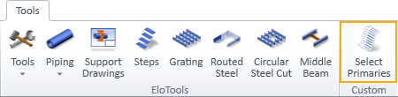
In the CADMATIC example project, on the Tools tab, the Select Primaries button opens a dialog where the support designer can enable automatic insertion for multi-pipe clamps, and the setting can be changed whenever necessary:
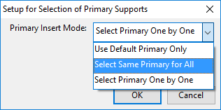
The options are:
- Use Default Primary Only – The wizard selects the primary support based on Short Code ("su4").
- Select same Primary for All – Select this option when the support construction only supports pipes that use a multi-clamp and all the pipes fit in a single multi-clamp.
- Select Primary One by One – Select this option when the support construction has both normal primary supports and multi-clamps, or when there are several multi-clamp sizes, such as one 2-pipe multi-clamp and one 5-pipe multi-clamp, in the same support.
Multi-pipe clamps as primary supports
Using hangers as primary supports
Hanger supports typically consist of a clamp that holds the pipe in place and a hanger rod that is attached to a suitable construction above the pipe. A designer who is inserting a hanger support into the model must be able to define the length of the rod based on the distance between the clamp and the support position above the pipe. Support Designer can use a Standard Component with instance parameters to implement a Catalog Part for hanger-type primary supports.
Hanger-type supports can be created in the same way as normal primary supports—by using the Construct tool of Support Designer or by running a support wizard. When a designer inserts a new hanger support into the model, the 3D object is created using the default instance parameter values, but the designer can use the Instance Parameters tool to edit the values as appropriate, and define, for example, the correct length of the hanger rod. The instance parameter values can also be changed later, as described in Editing instance parameters of supports.
For general information on instance parameters, see Instance Parameters.
For information on how to enable instance parameters for hanger supports, see Hangers as primary supports.
Editing instance parameters of supports
You can use the Edit Instance Parameters dialog to specify the dimensions of a support that uses instance parameters. You can set the dimensions when first inserting a new support to the model, and you can also edit the values later, as described below.
Do the following:
-
Open the Supports dialog of the required discipline, as described in Pipe, duct, and cable tray supports.
-
Select the support construction that contains the support to be modified.
-
In the Primary section, click Construct. The Construct Primary dialog opens.
-
Click Instance Parameters, pick the support object from the model, and press Enter. The Edit Instance Parameters dialog opens.
-
Set the required instance parameter values and click OK.
-
Close the Support Designer.
Managing the COS status of location plans and supports
The Manage COS Status function of Support Designer allows you to manage the COS status of objects and object groups associated with a location plan or support. You can use it for the following:
- To see the current COS status of each object or object group (location plan, support, model object, custom support drawing) and to browse the object hierarchies.
- To request and relinquish the ownership of objects and object groups.
- To check out and check in objects and object groups.
You must always check out the Support Designer objects that you want to modify and that requires their ownership to be on your local COS server. Especially in large, replicated projects the ownerships in a given object hierarchy can be dispersed to several COS servers, which might be on purpose or accidental. Using the COS status tool, you can try to transfer the required ownerships to your local server, and if that is not possible, at least you can see where the ownerships are and can then try to get the respective owners to relinquish the objects.
Do the following:
-
On the Piping, Ducting, or Cabling tab, select Support > Location plans. The Support Designer: Location Plans dialog opens.
-
Do one of the following:
-
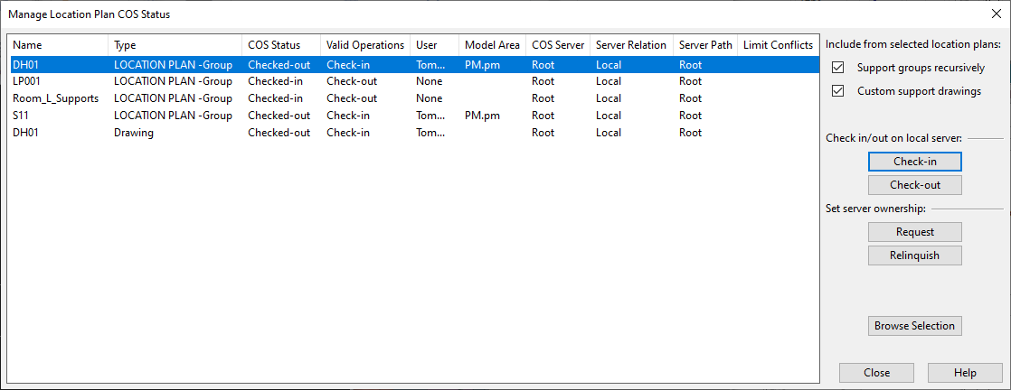
To manage the COS status of a location plan, select the location plan and click Manage COS Status. The Manage Location Plan COS Status dialog opens.
-
To manage the COS status of a particular support construction, click the pipe
 , cable tray
  , or air duct
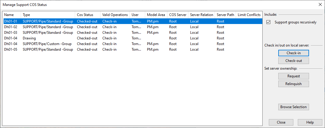
  button to open the respective Supports dialog, then select a support construction and click Manage COS Status. The Manage Support COS Status dialog opens.
-
-
The location plan or support you chose before opening the COS status dialog is selected in the list. The list pane displays the current status of each item and other relevant information.
The columns of the status management dialog:
Column
Description
Name
The name (position ID) of the item. Location plan (group) and the associated location plan drawing always have the same name.
Type
Displays whether the item is a location plan group or location plan drawing.
COS Status
The current status: "Checked-in" or "Checked-out".
Valid Operations
The possible action: "Check-in" or "Check-out".
User
The name of the user, if checked out.
Model Area
The name of the Plant Modeller model area where the item is checked-out.
COS Server
The name of the owning server, that is, the COS server which owns the selected object. For the project root this is a generic "Root", for replicas the true name of the server is shown.
Server Relation
Displays where the owning server is located:
- Local – The server that the Plant Modeller session is connected to.
- Upstream master – Any server above my local server in the same server tree branch.
- Downstream replica – Any server below my local server in the same server tree branch.
- In another branch – The owning server is in another server tree branch.
Server Path
The path in the COS server hierarchy, from the project root to the current owning server, using the colon ":" as the separator character.
Limit Conflicts
The Limit Conflicts column of supports indicates if the location of the object in the 3D model is such that it prevents the COS status of the object to be changed.
When an object is owned by the local server, the user can check out the object only when it is completely inside the 3D box that is available to the user (there can be several factors that limit the user's model area within the project space). If the object intersects the model area's boundaries, check-out is not possible.
Hold down Ctrl or Shift to select additional items from the list.
-
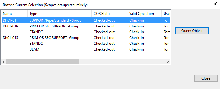
Select Browse Selection to open a dialog that lists all individual objects and object groups that are part of the hierarchy of the currently selected items. You can see complete object properties by selecting an object from the list and clicking Query Object.
-
In the options section, you can adjust the scope of the COS status changes to be performed on the items you have selected:
-
Support groups recursively – When selected, the COS status changes are applied to all members of the selected group hierarchies: to the location plan groups (if managing location plan statuses), to the support groups, and to the model objects that are assigned to the support groups.
If the option is not selected, the COS status changes are only applied to the selected location plan group or drawing, or to the selected support.
-
Custom support drawings – This option is only available for location plans. When selected, the COS status changes are applied to the support drawings of custom supports, if possible. (The name of the drawing is the same as the name of the custom support.)
-
-
Perform the required COS operation on the selected items:
- Select Check out to check out the items to the local server.
- Select Check in to check the items in again.
- Select Request to request ownership from the owning server.
- Select Relinquish to relinquish ownership to the server again.
-
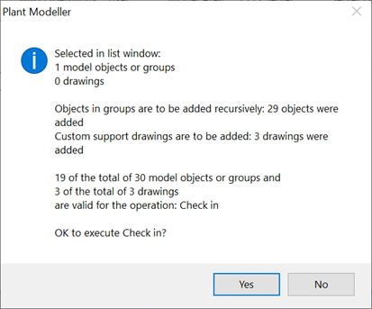
Before making the requested status change, the program makes a feasibility analysis and shows a report that indicates whether the action would be possible for all the directly and indirectly selected objects and drawings.
Select Yes to complete the action, or select No to cancel the request.
Managing the fastening materials of supports
In CADMATIC, the fastening materials of supports—bolts, nuts and washers—do not have a physical 3D model, but they can be defined in Support Designer and included in the Bill-of-Materials list.
Prerequisites
- Project administrator has defined the required fastening materials for the project, as described in Fastening materials for supports.
Do the following:
-
Open the Supports dialog of the required discipline, as described in Pipe, duct, and cable tray supports.
-
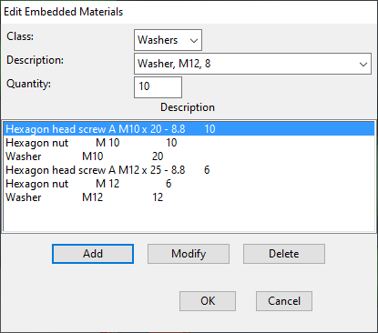
In the Secondary section, click Fastening Materials. The Edit Embedded Materials dialog opens.
-
To add materials to the list, do the following:
-
In the Class field, select the appropriate material class, such as Bolts, Nuts or Washers.
-
In the Description field, select the material to use.
-
In the Quantity field, select how many instances of the material to add.
-
Click Add.
-
-
To change the material or quantity of a listed item, select the item, make the required changes, and click Modify.
-
To remove a listed material, select the item and click Delete.
Generating a BOM list for location plans
Bill-of-Materials listings can be done with the standard Listing tool on the Documents tab.
Generating support drawings automatically
In Support Designer, you can create a drawing for a support and then use the standard Plant Modeller drawing tools to finalize the document.
For some supports, you can also generate drawings completely automatically. If the EloTools option was selected when installing CADMATIC, you can use the Support Drawings function of EloTools to generate support drawings as described below.
Prerequisites
- The displaying of datum point has been enabled, if required, as described in Datum point in support drawings.
Do the following:
-
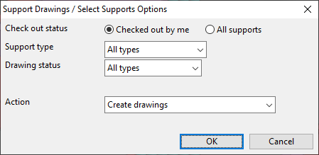
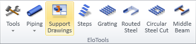
On the Tools tab of Plant Modeller, in the EloTools group, select Support Drawings. The Support Drawings / Select Supports Options dialog opens.
-
Select the required options.
-
Check out status – Normally this should be set to Checked out by me (default) because it is not possible to add part numbers to objects you do not own; this is also required for showing the datum point of the support.
You can set this to All supports only if part numbers are not enabled in the interactive configuration and Action is not set to update parameters.
-
Support type – Select whether to generate support drawings for all types (default) or only for either wizard or non-wizard drawing types.
-
Drawing status – Select whether to generate support drawings for all types (default) or only when a drawing either already exists or does not exist yet.
-
Action – You can set this to:
-
Create drawings – Creates the drawings but does not update part numbers.
-
Create drawings and update parameters – Creates the drawings and updates part numbers.
Note: You must select this option to display the datum point in drawings.
-
Update parameters only – Updates the part numbers but does not create drawings.
-
-
-
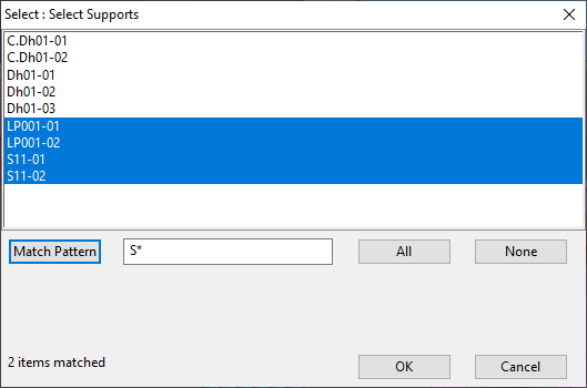
Click OK. The Select Supports dialog opens.
-
Select the supports for which to generate a drawing. You can use the Match Pattern field to select supports incrementally. For example, you can first select all that match "LP*" and then all that match "S*".
-
Click OK. The drawings are generated.
-
You can now open the generated drawings from Documents > Drawings.